الأحداث


LOW.

In a 'Schmitt trigger' circuit there are two different switching
thresholds. If Vin is slowly increased starting from 0 V, the output
voltage snaps from HIGH to LOW when Vin reaches a level equal to 2/3 of
the power supply voltage. Once this level has been exceeded, decreasing
Vin does not affect the output until Vin drops below 1/3 of the power
supply voltage. (If an input change in one direction produces a
different result from a change in the opposite direction, the circuit is
said to show hysteresis.)
If a filament lamp is connected between the positive power supply rail
and the output, as shown above, current flows through the lamp when the
output voltage is LOW. In other words, the lamp lights when the input
voltage is HIGH.
If you connect the lamp between the output and 0 V, the circuit will
still work, but the lamp will light when the input voltage is LOW:
Note that, in both versions of the circuit pins 2 and 6 are joined
together. The circuit can be simplified by omitting the 10 nF bypass
capacitor, and will continue to work when the RESET input, pin 4 is left
unconnected.
Some people are very fond of this circuit and use it whenever a
transducer driver is required. However, with a HIGH/LOW digital input
signal the same result can be achieved more obviously and at lower cost
using a transistor switch circuit
plitude in comparison with the sine and sawtooth waveforms. Check out the pictures below.

This is the top of the circuit board. I used some non-coppered
perfboard I had lying about to build the circuit on. Whenever I use
perfboard, I like to mark up my perfboard with some fine point Sharpie
markers and get all the connections worked out before I actually
construct the circuit.

I find it easier to do it this way. This is the back side. It's a little
more challenging using this type of perfboard over the copper padded
type.

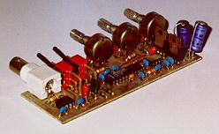
Here is a view of the front. The enclosure comes from a defunct 4-way
data switch box. I gutted it and created some graphics for the
faceplate. It measures 7.5"x2.25"x5" deep. For the frequency range
switch, I used a recycled rotary switch from an old parallel port A/B
switch box. To make it work with this circuit, I had to disassemble it
and rearrange the insides a little bit, but now it does exactly what I
want it to. (I know, I could have just bought a new rotary switch, but I
had this switch lying around...) Since I am using a single female BNC
jack and a single 1/4" jack wired in parallel, I decided to use three
SPST switches to switch between the different waveforms. One of the
switches will be a on-center off-on type. I figure the middle position
would make a nice "kill switch" which will prevent any waveforms from
reaching the output jacks. I like the idea, because if I don't want any
output, I can just flip that switch and leave the unit powered up. Of
course, one could just use another rotary switch with a SPST switch that
could act as a kill switch as well. I used the SPST switches mainly
because I had a bunch of them lying around waiting for a new home...
This homebrew function generator isn't as fancy or accurate as the ones
that are on the market, but for a do-it-yourselfer hobbyist type, it's
adequate. I have found that the sine wave isn't totally accurate when I
switch between frequency ranges, but I have incorporated a pot which
corrects any waveform offsets, so it still quite useable and pretty
accurate. Not too bad for a $20 project.